Tuesday, January 31, 2012

Flying Experiments

I managed to go flying last Friday after work. Since no one else was able to come along, I decided to do some experiments with the camera.

Last time I mounted the camera on the rear window pointing out. This time I pointed it toward me, instead of out the window. I did a time-lapse of the first half and later on an actual video of the landing.

Not too interesting, but I figured I would share them  here.


Saturday, January 21, 2012

CC2500 Project (Part 6) - Reorganizing

This post is mostly about software, so I'll keep it short.

I re-arranged most of the code so it hopefully makes more sense. My goal is to make the main code hardware agnostic. That way if you want to use a different device, you just change which drivers you're using, but your main code stays the same. Eventually I'd like to be able to support multiple devices from multiple manufacturers.

For a much better description, check out the page (and code) on github here: https://github.com/alvarop/msp430-cc2500
(The README file should have some information)

To keep things interesting, here's a quick video on what I was able to do with the current setup. The RGB LED controller(msp430g2452 + cc2500) is wirelessly connected to the PC(msp430g2533 + cc2500 + usb-to-serial converter).


Friday, January 20, 2012

CC2500 Project (Part 5) -- SPI Problem Solved!

So I wrote last week about getting UART working on the MSP430G2533 but having major problems with the SPI interface... I was so frustrated that I caved in and purchased a Salae Logic analyzer. It finally arrived today, and I had a chance to test it.

Salae Logic in action!
As soon as I opened the box, I connected it to sniff the SPI lines between my msp430 and cc2500 radio. It took me maybe 10-15 minutes to set up everything, including the Salae software to decode SPI on the fly. I ran my radio-setup code and observed the logic output. It seemed like something was happening, but it wasn't quite working.

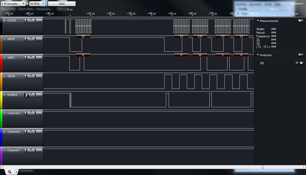
First capture with msp430g2533
To get a better idea as to what it should look like, I connected my msp430g2452, which had a working SPI link with the radio. The first thing I noticed was an error saying that the clock polarity was inverted. Aha! So the SPI clock on the 2533 was low when idle, while the specification says it's supposed to be high.
So I went into the datasheet and figured out how to fix the clock problem.

'Correct' capture with the msp430g2452
I tried it again and, not surprisingly, it failed. Looking more carefully at the MISO/MOSI lines, I realized that they were backwards! Turns out that the SPI IO pins do not match between the msp4302533 and the 2452. I swapped two wires and everything started working!

While I was really happy I fixed the problem, this means that my previously mentioned PCB will only work with one of the two devices. My plan is to use the more expensive 2533 as a PC-to-radio bridge, since it has both a hardware UART to talk to the pc and hardware SPI to talk to the radio. The cheaper 2452 only has one SPI to use the radio.

Launchpad with cc2500 Radio and Salae logic
In the end, I'm still happy. The Salae logic was extremely helpful and easy to use. It took me less than an hour to solve a problem I hadn't figure out in two days! Now I will be able to focus much more time in coming up with good radio libraries, instead of debugging silly problems.

Sunday, January 15, 2012

CC2500 Project (Part 4)

I haven't been working on this project lately, but I finally got back to programming yesterday. I got the MSP430G2533 which has both hardware UART and SPI. This one will act as a bridge between the PC and the CC2500 radio. It could also be used to drive a serial LCD.

I managed to get the UART working, but for some reason I'm having trouble with the SPI communication with the radio. I've been wanting to get a Saleae Logic analyzer for a while. Now I have a reason!

On the hardware side, I put together a breakout board for the MSP430 and CC2500. It only has a few passives and two LED's along with the MSP430 and a header for the CC2500 module I've been working with. I put them on opposite sides to save space, but that caused some problems.


I want to have the radio and antenna exposed, which means the MSP430 needs to go on the other side. Unfortunately, this means that the pins are all backwards(Top-right is pin 1.) I'll just have to keep that in mind while breadboarding.

Hopefully I'll get the Saleae Logic soon so I can iron out these SPI problems. Once that's done and I have these boards, you should start to see some much nicer projects (and better code!)