I'm moving my blog to my own server + wordpress.
You can see it at http://alvarop.com
Once I figure out how to keep the old links working, I'll get rid of blog.alvarop.com
Saturday, February 25, 2012
Tuesday, February 14, 2012
CC2500 Project (Part 8) - Downsizing
I received my PCB's yesterday (From Laen at dorkbotpdx.org, of course!). I spent last night attempting to solder all the surface mount components (and for the most part, failing miserably). I need to get some solder paste and a small oven for the next batch...
After soldering all of the passive components and msp430's, I began the first set of tests. First I checked to see if all of the connections were good with my multimeter. Once I fixed any problems I found there, I tried powering the board and connecting with the programmer/debugger. Surprisingly, it worked almost immediately! (I had to connect power to the correct pins first...)
The next test consisted of flashing the two LED's. Unfortunately, only one of them worked... I put together two devices, but LED1 didn't work on either one! I decided to call it a night then. After getting back from work today, I continued my debugging session. Turns out that one resistor wasn't soldered correctly (my multimeter test worked because I was pressing it down with the probe) and the second was a badly soldered LED.
I continued the same test by toggling all of the IO pins (Port 1 and 2). I looked at each one with the oscilloscope to make sure it was toggling correctly. As soon as I started, things went downhill. Some pins toggled, but most didn't. I went back and re-soldered all of the msp430 pins and tested them again. It was better, but half of the pins still didn't toggle. I decided to probe the microcontroller pins directly, but they weren't doing anything either. It had to be a software problem. It turns out that I was only toggling pins 0-3, and not 4-7. Once I realized my stupid mistake, I corrected it and everything started working.
The final step consisted of soldering the CC2500 radios. Unfortunately I didn't think my design through very well, since the radio modules have the crystal oscillator at the bottom, so it kind of sticks out at an angle. I changed the wireless RGB LED controller code to run on the msp430g2412 (which is what these use) and re-programmed them. Amazingly, the radios worked on my first try.
I decided my old RGB LED controllers were taking up too much space on the breadboards, so I replaced them with the newly created modules. They take up very little space and work just as well. I'm thinking of making the switching DC/DC power supply just as small and hopefully integrating it with the current device.
Now that I have a semi-decent platform, I can start working on writing some awesome radio libraries. (Once I put together more radios of course...) I want to have a full home-automation system going in a few months. I'll keep posting updates here.
 |
| Those components are tiny! |
 |
| This is why I like my glass desk. |
 |
| Entire device MSP430 + CC2500 Radio |
 |
| New device in front of prototype it's replacing. |
 |
| Look at all that free space! |
 |
| Another device next to the components it replaced. |
Sunday, February 12, 2012
CC2500 Project (Part 7) - More Lights and Power Supplies!
Here's another quick update (with lots of pictures and a video!) I ordered another RGB LED strip from adafruit in order to test how my system works with multiple devices. I don't have my PCB's yet (I shipped them to NY by mistake...), so I had to build everything on breadboards.
 |
| My messy work space. |
 |
| Device with linear regulator (left) and DC/DC switching regulator (right). |
 |
| That's a huge 0.33 Ohm resistor (It's all I had...) |
 |
| Dropping from 12v to 3.3v generates a LOT of heat. (Thankfully, I had a heat sink) |
 |
| RGB LED Driver (There are some surface mount resistors and transistors on the other side) |
 |
| Shelf plus LED strip. |
 |
| I'm not sure what that is called(counter-top?), but that's where I hung the second strip. |
I tried getting a video of the whole setup, but my camera doesn't seem to like low light situations. It looks much better in person!
Tuesday, February 7, 2012
Smart Meter Fun (Part 1)
My current apartment has one of those 'smart' electric meters that can communicate with the power company directly over the power lines. A few months ago, I found out about a smartmetertexas.com, which lets you register and get logs of your power usage in 15 minute increments. I thought that was really awesome and signed up. The concept is really cool, but unfortunately, their user interface isn't that great. It does, however, allow you to export all of that information in one large csv file.
After getting the file, I decided to write a small python script to get some more information about my usage. Right now it doesn't do much, but it shows me information like daily usage, hourly (ok, 15 minute-ly) averages, and weekday averages.
From looking at this data, I use the most energy on Saturdays (Washer, dryer, more tv than usual, etc...). It also seems that I use the most energy from 7:30-7:45am. That's usually when I'm making breakfast and using the stove.
The next step will be to figure out how to automate the graphing process. Right now, I export to csv files and then plot with excel. Maybe I can use gnuplot or some python extension to do it all at once.
I'll be putting the code I'm using up on github: https://github.com/alvarop/smartmetertexas_reader
After getting the file, I decided to write a small python script to get some more information about my usage. Right now it doesn't do much, but it shows me information like daily usage, hourly (ok, 15 minute-ly) averages, and weekday averages.
 |
| Total energy usage per day in kWh |
 |
| Average energy usage in 15 minute increments from all of the days in the data set. |
 |
| Average energy usage per day of the week |
From looking at this data, I use the most energy on Saturdays (Washer, dryer, more tv than usual, etc...). It also seems that I use the most energy from 7:30-7:45am. That's usually when I'm making breakfast and using the stove.
The next step will be to figure out how to automate the graphing process. Right now, I export to csv files and then plot with excel. Maybe I can use gnuplot or some python extension to do it all at once.
I'll be putting the code I'm using up on github: https://github.com/alvarop/smartmetertexas_reader
Tuesday, January 31, 2012
Flying Experiments
I managed to go flying last Friday after work. Since no one else was able to come along, I decided to do some experiments with the camera.
Last time I mounted the camera on the rear window pointing out. This time I pointed it toward me, instead of out the window. I did a time-lapse of the first half and later on an actual video of the landing.
Not too interesting, but I figured I would share them here.
Last time I mounted the camera on the rear window pointing out. This time I pointed it toward me, instead of out the window. I did a time-lapse of the first half and later on an actual video of the landing.
Not too interesting, but I figured I would share them here.
Saturday, January 21, 2012
CC2500 Project (Part 6) - Reorganizing
This post is mostly about software, so I'll keep it short.
I re-arranged most of the code so it hopefully makes more sense. My goal is to make the main code hardware agnostic. That way if you want to use a different device, you just change which drivers you're using, but your main code stays the same. Eventually I'd like to be able to support multiple devices from multiple manufacturers.
For a much better description, check out the page (and code) on github here: https://github.com/alvarop/msp430-cc2500
(The README file should have some information)
To keep things interesting, here's a quick video on what I was able to do with the current setup. The RGB LED controller(msp430g2452 + cc2500) is wirelessly connected to the PC(msp430g2533 + cc2500 + usb-to-serial converter).
Friday, January 20, 2012
CC2500 Project (Part 5) -- SPI Problem Solved!
So I wrote last week about getting UART working on the MSP430G2533 but having major problems with the SPI interface... I was so frustrated that I caved in and purchased a Salae Logic analyzer. It finally arrived today, and I had a chance to test it.
 |
| Salae Logic in action! |
 |
| First capture with msp430g2533 |
To get a better idea as to what it should look like, I connected my msp430g2452, which had a working SPI link with the radio. The first thing I noticed was an error saying that the clock polarity was inverted. Aha! So the SPI clock on the 2533 was low when idle, while the specification says it's supposed to be high.
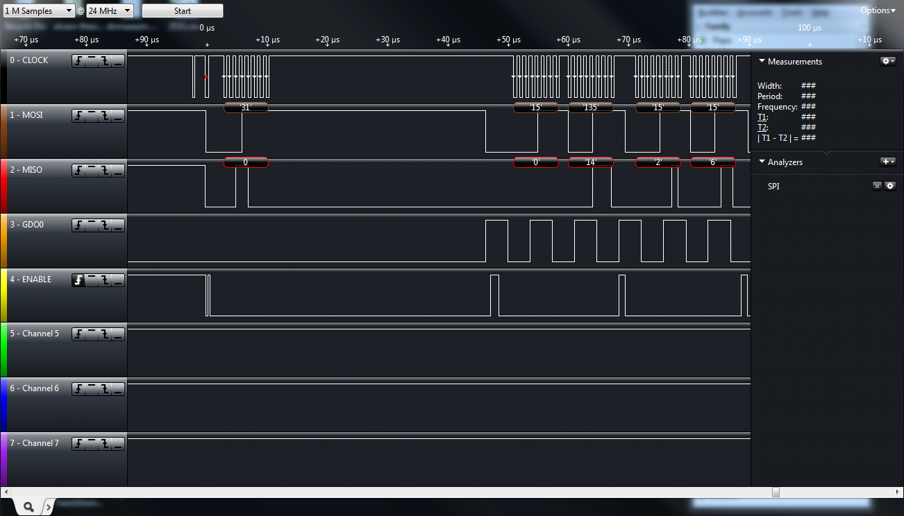 |
| 'Correct' capture with the msp430g2452 |
While I was really happy I fixed the problem, this means that my previously mentioned PCB will only work with one of the two devices. My plan is to use the more expensive 2533 as a PC-to-radio bridge, since it has both a hardware UART to talk to the pc and hardware SPI to talk to the radio. The cheaper 2452 only has one SPI to use the radio.
 |
| Launchpad with cc2500 Radio and Salae logic |
Subscribe to:
Posts (Atom)