I'm moving my blog to my own server + wordpress.
You can see it at http://alvarop.com
Once I figure out how to keep the old links working, I'll get rid of blog.alvarop.com
Saturday, February 25, 2012

Tuesday, February 14, 2012
CC2500 Project (Part 8) - Downsizing
I received my PCB's yesterday (From Laen at dorkbotpdx.org, of course!). I spent last night attempting to solder all the surface mount components (and for the most part, failing miserably). I need to get some solder paste and a small oven for the next batch...
After soldering all of the passive components and msp430's, I began the first set of tests. First I checked to see if all of the connections were good with my multimeter. Once I fixed any problems I found there, I tried powering the board and connecting with the programmer/debugger. Surprisingly, it worked almost immediately! (I had to connect power to the correct pins first...)
The next test consisted of flashing the two LED's. Unfortunately, only one of them worked... I put together two devices, but LED1 didn't work on either one! I decided to call it a night then. After getting back from work today, I continued my debugging session. Turns out that one resistor wasn't soldered correctly (my multimeter test worked because I was pressing it down with the probe) and the second was a badly soldered LED.
I continued the same test by toggling all of the IO pins (Port 1 and 2). I looked at each one with the oscilloscope to make sure it was toggling correctly. As soon as I started, things went downhill. Some pins toggled, but most didn't. I went back and re-soldered all of the msp430 pins and tested them again. It was better, but half of the pins still didn't toggle. I decided to probe the microcontroller pins directly, but they weren't doing anything either. It had to be a software problem. It turns out that I was only toggling pins 0-3, and not 4-7. Once I realized my stupid mistake, I corrected it and everything started working.
The final step consisted of soldering the CC2500 radios. Unfortunately I didn't think my design through very well, since the radio modules have the crystal oscillator at the bottom, so it kind of sticks out at an angle. I changed the wireless RGB LED controller code to run on the msp430g2412 (which is what these use) and re-programmed them. Amazingly, the radios worked on my first try.
I decided my old RGB LED controllers were taking up too much space on the breadboards, so I replaced them with the newly created modules. They take up very little space and work just as well. I'm thinking of making the switching DC/DC power supply just as small and hopefully integrating it with the current device.
Now that I have a semi-decent platform, I can start working on writing some awesome radio libraries. (Once I put together more radios of course...) I want to have a full home-automation system going in a few months. I'll keep posting updates here.
 |
| Those components are tiny! |
 |
| This is why I like my glass desk. |
 |
| Entire device MSP430 + CC2500 Radio |
 |
| New device in front of prototype it's replacing. |
 |
| Look at all that free space! |
 |
| Another device next to the components it replaced. |
Sunday, February 12, 2012
CC2500 Project (Part 7) - More Lights and Power Supplies!
Here's another quick update (with lots of pictures and a video!) I ordered another RGB LED strip from adafruit in order to test how my system works with multiple devices. I don't have my PCB's yet (I shipped them to NY by mistake...), so I had to build everything on breadboards.
 |
| My messy work space. |
 |
| Device with linear regulator (left) and DC/DC switching regulator (right). |
 |
| That's a huge 0.33 Ohm resistor (It's all I had...) |
 |
| Dropping from 12v to 3.3v generates a LOT of heat. (Thankfully, I had a heat sink) |
 |
| RGB LED Driver (There are some surface mount resistors and transistors on the other side) |
 |
| Shelf plus LED strip. |
 |
| I'm not sure what that is called(counter-top?), but that's where I hung the second strip. |
I tried getting a video of the whole setup, but my camera doesn't seem to like low light situations. It looks much better in person!
Tuesday, February 7, 2012
Smart Meter Fun (Part 1)
My current apartment has one of those 'smart' electric meters that can communicate with the power company directly over the power lines. A few months ago, I found out about a smartmetertexas.com, which lets you register and get logs of your power usage in 15 minute increments. I thought that was really awesome and signed up. The concept is really cool, but unfortunately, their user interface isn't that great. It does, however, allow you to export all of that information in one large csv file.
After getting the file, I decided to write a small python script to get some more information about my usage. Right now it doesn't do much, but it shows me information like daily usage, hourly (ok, 15 minute-ly) averages, and weekday averages.
From looking at this data, I use the most energy on Saturdays (Washer, dryer, more tv than usual, etc...). It also seems that I use the most energy from 7:30-7:45am. That's usually when I'm making breakfast and using the stove.
The next step will be to figure out how to automate the graphing process. Right now, I export to csv files and then plot with excel. Maybe I can use gnuplot or some python extension to do it all at once.
I'll be putting the code I'm using up on github: https://github.com/alvarop/smartmetertexas_reader
After getting the file, I decided to write a small python script to get some more information about my usage. Right now it doesn't do much, but it shows me information like daily usage, hourly (ok, 15 minute-ly) averages, and weekday averages.
 |
| Total energy usage per day in kWh |
 |
| Average energy usage in 15 minute increments from all of the days in the data set. |
 |
| Average energy usage per day of the week |
From looking at this data, I use the most energy on Saturdays (Washer, dryer, more tv than usual, etc...). It also seems that I use the most energy from 7:30-7:45am. That's usually when I'm making breakfast and using the stove.
The next step will be to figure out how to automate the graphing process. Right now, I export to csv files and then plot with excel. Maybe I can use gnuplot or some python extension to do it all at once.
I'll be putting the code I'm using up on github: https://github.com/alvarop/smartmetertexas_reader
Tuesday, January 31, 2012
Flying Experiments
I managed to go flying last Friday after work. Since no one else was able to come along, I decided to do some experiments with the camera.
Last time I mounted the camera on the rear window pointing out. This time I pointed it toward me, instead of out the window. I did a time-lapse of the first half and later on an actual video of the landing.
Not too interesting, but I figured I would share them here.
Last time I mounted the camera on the rear window pointing out. This time I pointed it toward me, instead of out the window. I did a time-lapse of the first half and later on an actual video of the landing.
Not too interesting, but I figured I would share them here.
Saturday, January 21, 2012
CC2500 Project (Part 6) - Reorganizing
This post is mostly about software, so I'll keep it short.
I re-arranged most of the code so it hopefully makes more sense. My goal is to make the main code hardware agnostic. That way if you want to use a different device, you just change which drivers you're using, but your main code stays the same. Eventually I'd like to be able to support multiple devices from multiple manufacturers.
For a much better description, check out the page (and code) on github here: https://github.com/alvarop/msp430-cc2500
(The README file should have some information)
To keep things interesting, here's a quick video on what I was able to do with the current setup. The RGB LED controller(msp430g2452 + cc2500) is wirelessly connected to the PC(msp430g2533 + cc2500 + usb-to-serial converter).
I re-arranged most of the code so it hopefully makes more sense. My goal is to make the main code hardware agnostic. That way if you want to use a different device, you just change which drivers you're using, but your main code stays the same. Eventually I'd like to be able to support multiple devices from multiple manufacturers.
For a much better description, check out the page (and code) on github here: https://github.com/alvarop/msp430-cc2500
(The README file should have some information)
To keep things interesting, here's a quick video on what I was able to do with the current setup. The RGB LED controller(msp430g2452 + cc2500) is wirelessly connected to the PC(msp430g2533 + cc2500 + usb-to-serial converter).
Friday, January 20, 2012
CC2500 Project (Part 5) -- SPI Problem Solved!
So I wrote last week about getting UART working on the MSP430G2533 but having major problems with the SPI interface... I was so frustrated that I caved in and purchased a Salae Logic analyzer. It finally arrived today, and I had a chance to test it.
 |
| Salae Logic in action! |
 |
| First capture with msp430g2533 |
To get a better idea as to what it should look like, I connected my msp430g2452, which had a working SPI link with the radio. The first thing I noticed was an error saying that the clock polarity was inverted. Aha! So the SPI clock on the 2533 was low when idle, while the specification says it's supposed to be high.
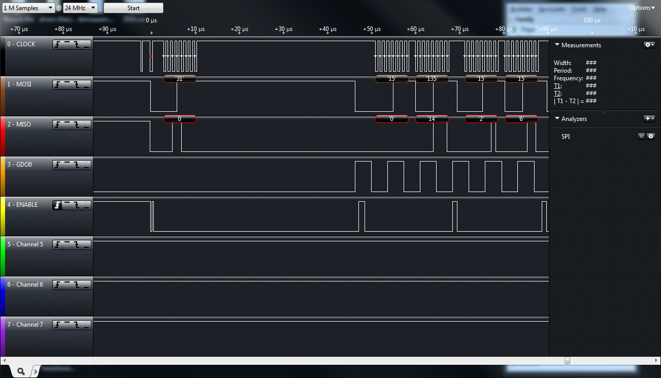 |
| 'Correct' capture with the msp430g2452 |
While I was really happy I fixed the problem, this means that my previously mentioned PCB will only work with one of the two devices. My plan is to use the more expensive 2533 as a PC-to-radio bridge, since it has both a hardware UART to talk to the pc and hardware SPI to talk to the radio. The cheaper 2452 only has one SPI to use the radio.
 |
| Launchpad with cc2500 Radio and Salae logic |
Sunday, January 15, 2012
CC2500 Project (Part 4)
I haven't been working on this project lately, but I finally got back to programming yesterday. I got the MSP430G2533 which has both hardware UART and SPI. This one will act as a bridge between the PC and the CC2500 radio. It could also be used to drive a serial LCD.
I managed to get the UART working, but for some reason I'm having trouble with the SPI communication with the radio. I've been wanting to get a Saleae Logic analyzer for a while. Now I have a reason!
On the hardware side, I put together a breakout board for the MSP430 and CC2500. It only has a few passives and two LED's along with the MSP430 and a header for the CC2500 module I've been working with. I put them on opposite sides to save space, but that caused some problems.

I want to have the radio and antenna exposed, which means the MSP430 needs to go on the other side. Unfortunately, this means that the pins are all backwards(Top-right is pin 1.) I'll just have to keep that in mind while breadboarding.
Hopefully I'll get the Saleae Logic soon so I can iron out these SPI problems. Once that's done and I have these boards, you should start to see some much nicer projects (and better code!)
I managed to get the UART working, but for some reason I'm having trouble with the SPI communication with the radio. I've been wanting to get a Saleae Logic analyzer for a while. Now I have a reason!
On the hardware side, I put together a breakout board for the MSP430 and CC2500. It only has a few passives and two LED's along with the MSP430 and a header for the CC2500 module I've been working with. I put them on opposite sides to save space, but that caused some problems.

I want to have the radio and antenna exposed, which means the MSP430 needs to go on the other side. Unfortunately, this means that the pins are all backwards(Top-right is pin 1.) I'll just have to keep that in mind while breadboarding.
Hopefully I'll get the Saleae Logic soon so I can iron out these SPI problems. Once that's done and I have these boards, you should start to see some much nicer projects (and better code!)
Tuesday, December 6, 2011
CC2500 Project (Part 3)
Here's an even smaller update!
Since the MSP430G2452 doesn't have a hardware UART, it's not very useful in communicating with the computer. I could use the bit-banging method to get 2400baud, but I didn't feel like figuring it out.
For my thesis, I implemented a serial-to-radio repeater using the EZ430-RF2500 and a USB-to-serial converter. I was able to modify the code to get it working. It ends up being a 19200baud link. For some reason, I can't get the processor to run at 16MHz without it giving me problems. Since I don't wan't to figure those out now, I'm running it at 1MHz, which prevents me from doing the usual 115200baud. (Not that I really need that speed.)
I then wrote a quick processing sketch to capture audio and send RGB values out the serial port to the microcontroller.
In short, I can now sync the lights to the music wirelessly!
Here's a quick video demo (As you can probably tell, I'm really happy it worked!):
Since the MSP430G2452 doesn't have a hardware UART, it's not very useful in communicating with the computer. I could use the bit-banging method to get 2400baud, but I didn't feel like figuring it out.
For my thesis, I implemented a serial-to-radio repeater using the EZ430-RF2500 and a USB-to-serial converter. I was able to modify the code to get it working. It ends up being a 19200baud link. For some reason, I can't get the processor to run at 16MHz without it giving me problems. Since I don't wan't to figure those out now, I'm running it at 1MHz, which prevents me from doing the usual 115200baud. (Not that I really need that speed.)
I then wrote a quick processing sketch to capture audio and send RGB values out the serial port to the microcontroller.
In short, I can now sync the lights to the music wirelessly!
Here's a quick video demo (As you can probably tell, I'm really happy it worked!):
Sunday, December 4, 2011
CC2500 Project (Part 2)
Here is a quick update on the project's progress.
Today I was able to get the radio libraries working better and actually set up constant radio communications across a room. I also wrote an RGB led controller using PWM and combined them together.
Here's a brief video of the result:
So far it's just one microcontroller generating RGB values and sending them to another one. Now I need to work on getting the PC to talk to the first microcontroller so I can control the lights with my computer.
Here's a demo of what I want it to do later. I have it working in the video, but it's fully wired and uses an ARM Mbed for control.
Today I was able to get the radio libraries working better and actually set up constant radio communications across a room. I also wrote an RGB led controller using PWM and combined them together.
Here's a brief video of the result:
So far it's just one microcontroller generating RGB values and sending them to another one. Now I need to work on getting the PC to talk to the first microcontroller so I can control the lights with my computer.
Here's a demo of what I want it to do later. I have it working in the video, but it's fully wired and uses an ARM Mbed for control.
Saturday, December 3, 2011
CC2500 Project (Part 1)
So I've started working on another project... This one includes microcontrollers and radios. The "goal" of the project is to have a very cheap 2.4GHz radio module and libraries to use it. I used the CC2500 radio module for my thesis project, but it was part of the EZ430-RF2500 development kit. The kit itself is nice, but at $20/device, it's not the cheapest.
My first though was to build my own board. I decided against it for several reasons. The first being that the CC2500 only comes in QFN packaging, which would make it a pain to hand solder. The second is that I have no experience designing RF circuits, which would probably result in the thing not working. The last reason is that I found a better alternative.
Turns out that the CC2500 is also used in some PS2 Guitar Hero controllers. They have the CC2500 chip on board and all the passive components (plus antenna!) I figured that would be much easier to work with. It has an SPI interface, so it can talk to most microcontrollers. The best part is that the whole thing costs less than a single CC2500 chip! I was able to get the whole thing for $1.80. (If you buy more than 1000, it only costs $1.35!) The only caveat is that the module has to be purchased from the manufacturer in China, which, at small quantities, makes the shipping a bit expensive.
 |
| CC2500 module with breakout board. |
Since the header for the board has 0.05'' separation, I had to make a breakout board for testing. I decided to test the radios with an MSP430G2452 microcontroller. I chose that one because is has hardware SPI and is available in 20-DIP package. The hardware SPI is really useful when interfacing to the radio at higher speeds (instead of bit-banging) and the DIP package makes it easy to work with (and fits into the launchpad).
 |
| MSP430G2452 in Launchpad with radio. |
I started writing my own radio libraries. TI provides a network stack called SimpliciTI, but it's bloated and I don't like it. For my thesis project, I wrote my own lightweight radio library, but it's all set up to work under linux and msp430-gcc. Since I want everyone to be able to use it, I'm porting it to work under TI's Code Composer Studio and putting it on github. So far I only have TI's demo code from slau144h working, but it confirms that all my wiring is ok and the radios work. Since I only have one launchpad, I replicated it on a breadboard. The code just sends a message when a button is pushed and toggles an LED when a message is received.
 |
| Breadboard with second radio and MSP430. |
Tuesday, November 29, 2011
West Texas Thanksgiving
So I had a few days off work for thanksgiving... Most people usually visit their family during that time, but due to a late change of plans, I ended up doing something else.
I found out that about 600 miles west of Houston is a town called Fort Davis, Texas. Near this town is the Davis Mountains State Park and the McDonald Observatory. Since I hadn't seen a clear night sky since I was a kid, I decided to drive over and check it out. (It's one of the places with the least light pollution in the area.)
Being the time-lapse nerd that I am, I decided to experiment with my camera and newly acquired suction-cup camera mount. The first experiment consisted of mounting the camera in the rear window and taking pictures every minute during the drive there.
NOTE: Watch the time-lapses in HD and full screen if possible, it really does make a difference, especially for the night ones.
Also, for more photos from the trip, check out my flickr set.
Unfortunately it didn't turn out so great...
My second experiment took place later that night near someone's ranch. I'm not sure if I was supposed to be there or not, but no one kicked me out (or saw me...) I found a radio telescope and did a very brief time-lapse of it with the stars in the background. I should have stayed longer, but I was tired from the drive and maybe a bit worried about being noticed.
The video is extremely short, but I thought it came out alright.
Since I went there to look at the night sky, I had to find stuff to do during the day. And by stuff I mean mounting the DSLR on the hood of my car and driving around while making more time-lapse videos. I used the same suction cup mount I mentioned previously. It held just fine while driving at speeds of 75+ mph! The actual device was purchased from filmtools.com. It worked great!
The first one happened during a drive from Marfa to Fort Davis.
Another one was from Fort Davis to Alpine.
There were other driving time-lapses, which you can see in my youtube channel.
The last was a more traditional time-lapse. I was driving and saw a nice field as the sun was setting. I set up my tripod and started taking photos.
I found out that about 600 miles west of Houston is a town called Fort Davis, Texas. Near this town is the Davis Mountains State Park and the McDonald Observatory. Since I hadn't seen a clear night sky since I was a kid, I decided to drive over and check it out. (It's one of the places with the least light pollution in the area.)
Being the time-lapse nerd that I am, I decided to experiment with my camera and newly acquired suction-cup camera mount. The first experiment consisted of mounting the camera in the rear window and taking pictures every minute during the drive there.
NOTE: Watch the time-lapses in HD and full screen if possible, it really does make a difference, especially for the night ones.
Also, for more photos from the trip, check out my flickr set.
 |
| Rear window mount. |
My second experiment took place later that night near someone's ranch. I'm not sure if I was supposed to be there or not, but no one kicked me out (or saw me...) I found a radio telescope and did a very brief time-lapse of it with the stars in the background. I should have stayed longer, but I was tired from the drive and maybe a bit worried about being noticed.
 |
| Radio telescope. |
Since I went there to look at the night sky, I had to find stuff to do during the day. And by stuff I mean mounting the DSLR on the hood of my car and driving around while making more time-lapse videos. I used the same suction cup mount I mentioned previously. It held just fine while driving at speeds of 75+ mph! The actual device was purchased from filmtools.com. It worked great!
 |
| Camera on car hood. Talk about trust! |
Another one was from Fort Davis to Alpine.
There were other driving time-lapses, which you can see in my youtube channel.
The last was a more traditional time-lapse. I was driving and saw a nice field as the sun was setting. I set up my tripod and started taking photos.
 |
| I can't seem to stay away from those "no trespassing" signs! |
Unfortunately I was on the side of the road, which produced some "interesting" effects due to car headlights... I tried moving the camera near the end to just point at the sky, but it's an ugly transition. Notice that Venus and the Moon are setting close to each other following the sunset. Again, for best results, watch the HD video in full screen!
Monday, November 21, 2011
Time-Lapse Experiments
I recently started experimenting some more with time-lapse videos while moving. I bought a suction cup mount for my DSLR and tested it out in my car.
I also tested it on a quick flight around the area. Since it was a bit gusty, the video shakes a lot. I tried out youtube's built-in stabilization feature and it seemed to do a good job!
You can see the original, much shakier one, here:
 |
| Testing mount on my window! |
Here's a very rough test of the car setup. I just wanted to see if the mount stuck to the window and didn't fall with the rough Houston roads.
You can see the original, much shakier one, here:
Friday, April 8, 2011
New Toys – Project Updates
I have been working on a few projects recently. Two of them involve having custom PCBs made. I'm currently waiting for them to arrive. In order to prototype and test the circuits, I had to order a bunch of parts, so I took advantage of the buying spree to get myself some better tools.
My favourite so far is my new Agilent U1251A Multimeter. After seeing the great review of the U1253A (which is just the OLED display version of this one, instead of LCD) on the EEVBlog, I found one for a decent price and decided to get it.
Another purchase was a vaccum base vice that can hold small-ish circuit boards. Since I'm going to be doing some surface mount soldering for my intervalometer project, I wanted to make sure I had something better than my helping hands to hold the boards.
I plan on doing full write ups of both of these projects once I finish, but here are a few details.
The first one is an intervalometer for my Canon camera which will use an Attiny13 microcontroller and a small CR2032 battery. It will have a configurable time interval and is only 1x1 inches.
The second one is a simple breakout board for my MBED microcontroller. I plan on using a few of these to permanently attach sets of sensors and other peripherals, while still being able to swap the main MBED board around. It's not the most exiting PCB, but I'm trying out different services to see which one I like better. I ordered the intervalometer board through BatchPCB and the mbed one from DorkbotPDX. I will also do a write-up about those when I get them.
One of my projects requires multiple temperature sensors. I ordered a bunch and tested one earlier. I cut up some phone wires and connected it there so I could put it out the window without exposing the whole board. It seems to be within 1 degree of the actual temperature, which is more than enough for what I'll need.
My favourite so far is my new Agilent U1251A Multimeter. After seeing the great review of the U1253A (which is just the OLED display version of this one, instead of LCD) on the EEVBlog, I found one for a decent price and decided to get it.
 |
| Agilent U1251A |
Another purchase was a vaccum base vice that can hold small-ish circuit boards. Since I'm going to be doing some surface mount soldering for my intervalometer project, I wanted to make sure I had something better than my helping hands to hold the boards.
 |
| New Vice |
I plan on doing full write ups of both of these projects once I finish, but here are a few details.
The first one is an intervalometer for my Canon camera which will use an Attiny13 microcontroller and a small CR2032 battery. It will have a configurable time interval and is only 1x1 inches.
 |
| Intervalometer PCB |
 |
| Mbed Breakout PCB |
 |
| MCP9701 Thermistor |
Tuesday, April 5, 2011
Hip MRI!
A few months ago, I found out that my school offers a diving class. I enrolled and was having fun for a few weeks until I messed up an entry off the 3m board and hurt myself. I didn't notice initially, but the next day my hip was hurting a lot.
I went to the doctor, got some x-rays, and began physical therapy. There was no bone damage, so they figured it would sort itself out with the therapy.
After a few months, some of the pain went away, but some still remains. (The injury happened in January!) The doctor recommended that I get an MRI Arthrogram. It's like any other MRI, except they put a contrast solution so they can see the soft tissue better (or something like that.) The catch is that they have to inject this contrast solution, with a huge needle.
I asked the imaging people (who were all really nice!) if I could have the images, so I'll use them here to explain. Here's a quick video someone else made about the contrast placement.
Now here is how mine went:
As usual the first step deals with your clothes. They only let you keep your socks on, along with those stylish hospital gowns. I then lay on a bed with a cool portable x-ray machine above. The first take an x-ray to make sure everything is aligned.
A few minutes after they tied down my foot so the leg position wouldn't change, the doctor arrived. They applied some of that yellow antiseptic stuff and let it dry and proceeded to stick me with a smaller needle to apply the anesthetic. It didn't really hurt much, I was expecting a burning sensation for a minute or so, but it was really quick. Now that my hip was all drugged up, they brought out the big one.
That needle needs to be long enough to reach the hip joint and wide enough to let the fluid through in a timely fashion. This step didn't quite hurt, but it sure felt strange. I could feel that they were pressing down, but couldn't quite pinpoint the source of discomfort. Once they started injecting the solution, I could feel it filling up.
The injecting part was really quick. I think they said it was only about 12cc's of solution. They then removed the needle and cleaned me up. After that was done, I went over to the MRI machine and spent ~45 minutes laying motionless. I kept drifting in and out of sleep, which is quite fun. Waking up inside an MRI machine working is quite something.
After that was done, I got my CD with all the images and headed home. The whole experience was not bad at all. I was slightly worried after reading other peoples reactions, but fortunately they did not apply.
I went to the doctor, got some x-rays, and began physical therapy. There was no bone damage, so they figured it would sort itself out with the therapy.
After a few months, some of the pain went away, but some still remains. (The injury happened in January!) The doctor recommended that I get an MRI Arthrogram. It's like any other MRI, except they put a contrast solution so they can see the soft tissue better (or something like that.) The catch is that they have to inject this contrast solution, with a huge needle.
I asked the imaging people (who were all really nice!) if I could have the images, so I'll use them here to explain. Here's a quick video someone else made about the contrast placement.
Now here is how mine went:
As usual the first step deals with your clothes. They only let you keep your socks on, along with those stylish hospital gowns. I then lay on a bed with a cool portable x-ray machine above. The first take an x-ray to make sure everything is aligned.
 |
| This is the first X-Ray. |
A few minutes after they tied down my foot so the leg position wouldn't change, the doctor arrived. They applied some of that yellow antiseptic stuff and let it dry and proceeded to stick me with a smaller needle to apply the anesthetic. It didn't really hurt much, I was expecting a burning sensation for a minute or so, but it was really quick. Now that my hip was all drugged up, they brought out the big one.
 |
| You can see the size of the needle here. |
 |
| Here's another X-Ray with the colors inverted. |
The injecting part was really quick. I think they said it was only about 12cc's of solution. They then removed the needle and cleaned me up. After that was done, I went over to the MRI machine and spent ~45 minutes laying motionless. I kept drifting in and out of sleep, which is quite fun. Waking up inside an MRI machine working is quite something.
 |
| One of many slices from the MRI. |
After that was done, I got my CD with all the images and headed home. The whole experience was not bad at all. I was slightly worried after reading other peoples reactions, but fortunately they did not apply.
Sunday, March 27, 2011
Slow Motion Roller Derby
I recently purchased a Casio EX-FH100 digital camera. Unlike most other point-and-shoots, this one can do high-speed video. It ranges from regular 720p HD video at 30fps to high-speed 120 fps(640 x 480), 240fps (448 x 336), 420fps (224 x 168), 1000fps (224 x 64). The resolution on the fastest two is pretty bad, but it's still fun to mess around with.
After testing the camera on myself jumping around (pretty lame), I decided to try it out at the ROC City Roller Derby bout at RIT. Here are some high-speed clips:
NOTE: I have over 100 of these, if you want to have them and use them, let me know! I don't have the skill or time to make a decent video using several of the clips.
For some reason, YouTube will only embed videos at 360p. Make sure you click on 480p to improve the quality. Enjoy!
This first video shows when Lethal Lorelei fell, injuring her ankle. (120fps)
Goldie Fox whips Hy DeMonic forward.(120fps)
Asa Clubs falls and calls off the jam after tripping.(120fps)
Gwar slips (240fps).
Toxin Dioxin and Thea Pocalypse race ahead. (120fps)
Toxin Dioxin is hit by Goldie Fox and calls off the jam.
Jammers off the start line. (120fps)
No skating in this one... Throwing t-shirts at the crowd. (120fps)
This last one is a mix of 30fps and 120fps. The girls did an extra jam after the bout finished, but this time with Thea Pocalypse wearing a camera on her helmet.
Please correct me if I screwed up anyone's name!
I also took some photos during the event, but since I was recording with the little camera, I didn't get too many. You can see them here: http://www.flickr.com/photos/apg88/sets/72157626237482515/
After testing the camera on myself jumping around (pretty lame), I decided to try it out at the ROC City Roller Derby bout at RIT. Here are some high-speed clips:
NOTE: I have over 100 of these, if you want to have them and use them, let me know! I don't have the skill or time to make a decent video using several of the clips.
For some reason, YouTube will only embed videos at 360p. Make sure you click on 480p to improve the quality. Enjoy!
This first video shows when Lethal Lorelei fell, injuring her ankle. (120fps)
Goldie Fox whips Hy DeMonic forward.(120fps)
Asa Clubs falls and calls off the jam after tripping.(120fps)
Gwar slips (240fps).
Toxin Dioxin and Thea Pocalypse race ahead. (120fps)
Toxin Dioxin is hit by Goldie Fox and calls off the jam.
Jammers off the start line. (120fps)
No skating in this one... Throwing t-shirts at the crowd. (120fps)
This last one is a mix of 30fps and 120fps. The girls did an extra jam after the bout finished, but this time with Thea Pocalypse wearing a camera on her helmet.
Please correct me if I screwed up anyone's name!
I also took some photos during the event, but since I was recording with the little camera, I didn't get too many. You can see them here: http://www.flickr.com/photos/apg88/sets/72157626237482515/
Sunday, March 20, 2011
Projects Update
I’ve decided to actually write about what I’ve been up to in the past few years. Today, I’m going to start with a project from the summer of 2006. I decided to go to DEFCON and take part in the defconbots competition. The main goal of the competition was to build a device that shot targets using autonomous control only. You can see the competition page here and the results. Unfortunately, I didn’t start working on it until two or three weeks before.
Here’s a brief description of how it happened. Since I was right out of high school, my budget was extremely limited. I decided to get a webcam mount with two servos and a USB servo controller, along with a really cheap BB gun.
After receiving the gun, I took it apart to figure out how it worked. It was basically a DC motor with some gears pulling back a spring that loaded, then fired, the BBs
Instead of buying a webcam, I took one from my dad and (after some modifications) mounted it in front of the gun.
At the time, my knowledge of programming was limited to PHP and VisualBasic. I figured out how to talk to the webcam and servo controller using VB and proceeded to write my aiming program. I had no idea about any image processing algorithms or anything like that, so I had to make it very simple. The targets were lit by infrared LED’s, and by using a filter in front of the webcam, I was able to isolate IR light from everything else. My high tech filter consisted of some developed film. After going through the filter, infrared light showed up as white pixels, while everything else was red or black. This allowed me to “find” IR light by counting white pixels in the image. I divided the image into a grid and counted how many white pixels were in each section. After figuring out which square had the most white pixels, I would move the gun in that direction. Once the most white pixels were in the center of the image, the gun would fire until the lights disappeared.
I tried a few different methods for firing the gun, but ended up going with the simplest. I connected another servo and glued a temporary switch to it. All I needed to do to fire was move that servo so it would push the button and close the circuit driving the DC motor in the gun.
The gun was not designed to hold too many BBs, so I added a parmesan cheese container to hold more. After everything (almost) worked, I packed it in a box and flew to Vegas. The TSA people were rather intrigued when they searched my luggage, but let me through after a few minutes.
The actual competition was a lot of fun. I came in 5th place (out of 6), but had a lot of fun doing it. Some of the competition consisted of university senior design projects with awesome equipment, so I really had no chance. Here are some photos from the competition. These last two photos were not taken by me. I can’t find who took the second one, so if it’s you, let me know so I can give appropriate credit!
Oh, I also added an “about me” page over here.
Here’s a brief description of how it happened. Since I was right out of high school, my budget was extremely limited. I decided to get a webcam mount with two servos and a USB servo controller, along with a really cheap BB gun.
 |
| One of three BB guns. |
 |
| USB Servo Controller |
 |
| Firing Mechanism |
 |
| The Guts |
 |
| Cannibalized Webcam |
 |
| Gun with Mount and Webcam |
 |
| Fancy IR Filter and Laptop with Aiming Program |
 |
| Firing Servo |
The actual competition was a lot of fun. I came in 5th place (out of 6), but had a lot of fun doing it. Some of the competition consisted of university senior design projects with awesome equipment, so I really had no chance. Here are some photos from the competition. These last two photos were not taken by me. I can’t find who took the second one, so if it’s you, let me know so I can give appropriate credit!
 |
| During Competition 1 |
 |
| During Competition 2 |
Sunday, September 12, 2010
Not-so-Quick Update
I still haven’t written about my Svalbard trip. Thankfully, I took some notes while I was there, so I will not forget the important details by the time I do write it.
Stockholm
My last week in Finland was great. I worked more than usual in order to have my final presentation on Wednesday August 25th. The next day I left Tampere and went to Turku to catch an overnight cruise to Stockholm with several friends. I had never been on a cruise before, so that was a nice experience. The next day we walked around Stockholm, had some delicious breakfast, and visited some museums. That afternoon, my friends returned to Finland, and I stayed in Stockholm for another night.
Photos from Stockholm.

London
I left Stockholm on my way to Belfast on Saturday August 28th. My flight had a layover in London before arriving to Belfast. Unfortunately the airplane from Stockholm was late arriving and had technical problems, so my first flight was delayed. When I did arrive to London, it was too late, so I British Airways got me a hotel room and some meal tickets until the next flight Sunday morning.
Belfast
I arrived to Belfast in the morning and two friends picked me up at the airport. We then had a traditional Irish fry-up for breakfast at my friend’s house. It was his birthday, so the nice breakfast was part of the celebration. We later took a bus tour around Belfast, where I learned quite a lot about the history. We stopped along the way at some Indian music festival and ended up in a milkshake place. I think there were over 100 different shakes, so we each ordered one. They were delicious! Later that night we went to an open air concert of some cover band for another band I don’t remember the name of. I do remember that Niamh Kavanagh, the Eurovision 1993 winner from Ireland, was singing. Even though I knew none of the songs, I enjoyed the music. The next morning I took a bus to Dublin.
Photos from Belfast.

Dublin
Another friend picked me up at the bus station in Dublin. We walked around the city for a bit but eventually ended up at the movie theatre watching Toy Story 3. Later on we went south to Dún Laoghaire and walked around there for a while.
Cambridge
I took the Swift ferry from Dublin to Holyhead in the morning of the 31st. I then took the train to London, where I got on another train to Cambridge. That night I ended up at the Cambridge Skeptics in the Pub meeting at the Maypole where I was able to meet Rebecca Watson after her presentation. The next morning, my friend arrived to Cambridge from further north. We walked around Cambridge for most of the day. I learned about all the colleges and visited the Botanical Gardens, which were really nice.
Trip Home
On Thursday September 2nd, I took a train from Cambridge to London and then the tube to the airport. I waited for several hours at the airport before flying to NYC. I spent the night in NYC before flying home to Rochester the next morning.
Stockholm
My last week in Finland was great. I worked more than usual in order to have my final presentation on Wednesday August 25th. The next day I left Tampere and went to Turku to catch an overnight cruise to Stockholm with several friends. I had never been on a cruise before, so that was a nice experience. The next day we walked around Stockholm, had some delicious breakfast, and visited some museums. That afternoon, my friends returned to Finland, and I stayed in Stockholm for another night.
Photos from Stockholm.
London
I left Stockholm on my way to Belfast on Saturday August 28th. My flight had a layover in London before arriving to Belfast. Unfortunately the airplane from Stockholm was late arriving and had technical problems, so my first flight was delayed. When I did arrive to London, it was too late, so I British Airways got me a hotel room and some meal tickets until the next flight Sunday morning.
Belfast
I arrived to Belfast in the morning and two friends picked me up at the airport. We then had a traditional Irish fry-up for breakfast at my friend’s house. It was his birthday, so the nice breakfast was part of the celebration. We later took a bus tour around Belfast, where I learned quite a lot about the history. We stopped along the way at some Indian music festival and ended up in a milkshake place. I think there were over 100 different shakes, so we each ordered one. They were delicious! Later that night we went to an open air concert of some cover band for another band I don’t remember the name of. I do remember that Niamh Kavanagh, the Eurovision 1993 winner from Ireland, was singing. Even though I knew none of the songs, I enjoyed the music. The next morning I took a bus to Dublin.
Photos from Belfast.
Dublin
Another friend picked me up at the bus station in Dublin. We walked around the city for a bit but eventually ended up at the movie theatre watching Toy Story 3. Later on we went south to Dún Laoghaire and walked around there for a while.
Cambridge
I took the Swift ferry from Dublin to Holyhead in the morning of the 31st. I then took the train to London, where I got on another train to Cambridge. That night I ended up at the Cambridge Skeptics in the Pub meeting at the Maypole where I was able to meet Rebecca Watson after her presentation. The next morning, my friend arrived to Cambridge from further north. We walked around Cambridge for most of the day. I learned about all the colleges and visited the Botanical Gardens, which were really nice.
Trip Home
On Thursday September 2nd, I took a train from Cambridge to London and then the tube to the airport. I waited for several hours at the airport before flying to NYC. I spent the night in NYC before flying home to Rochester the next morning.
Subscribe to:
Posts (Atom)